
Power Distribution in Your Building: Fulfilling Its Electrical Potential
By Brian McDivitt, PE
According to the National Electrical Code, a branch circuit refers to “the circuit conductors between the final overcurrent device protecting the circuit and the outlet(s).” A branch circuit is the last step of building power distribution before you plug in a device or appliance.
But how do you determine and understand what voltage is available for your appliance? This article is the first in a three-part series about power distribution that helps you understand the basics of circuit voltages, distribution configurations, and configuration preferences.
Editor’s Note: This is the first in a three-part series on power distribution systems. Read part two and part three.
The 120V Circuit
For the most part, devices such as phone chargers, lampstands, and vacuums, that you plug into a wall outlet operate nominally at 120V. A 120V-branch circuit is single-phase, meaning that the circuit contains at least two wires. One wire is the hot wire (L, for line) and one is the neutral wire (N). More recent circuit designs include a third wire for ground (G). The common three-prong outlet used for 120V devices has a configuration called NEMA 5-15R (pictured above left).
Voltage, also known as electrical potential, is measured between L and N for a 120V circuit. This is called line-to-neutral voltage. Although electrical current does pass through the neutral wire to complete the circuit, the electrical potential of the neutral ideally remains at the ground. If you measure the voltage between N and G, it should always be very close to 0. The circuit’s energy is dissipated through the load connected between wires L and N.
Other Voltages for Power Distribution
What if an appliance requires a voltage other than 120V? Building owners and tenants often want to install an appliance, such as an oven, a clothes dryer, or an espresso machine, with a high-power consumption. These and other similar appliances use a voltage other than 120V and often have a few voltages to choose from.
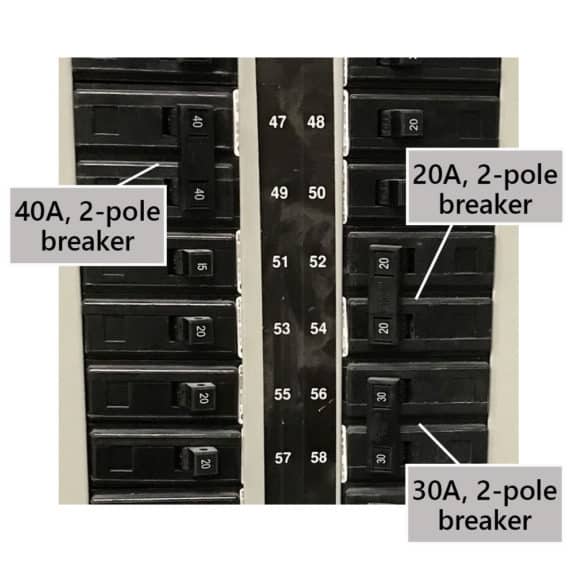
From the same panel that feeds 120V circuits, you also have access to either 208V or 240V. A 120V-circuit has only one hot wire, and therefore only a one-space (also referred to as single-pole) breaker is used in the panel. If you use a higher voltage of 208V or 240V, the breaker will have two or three poles for the number of hot wires used in the circuit. Voltage measured between hot wires is called line-to-line voltage. Depending on the equipment’s power needs, these types of circuits may or may not require the presence of a neutral wire, but they almost always include a ground wire.
Although less familiar than 120V, the 277V (line-to-neutral) is another commonly used single-phase circuit voltage. We use circuits of this voltage to light large commercial buildings. If this voltage is available for a circuit, the source panel will also have 480V (line-to-line) available. A 480V circuit may use two or three poles, depending on power requirements.


What Voltage Should You Use?
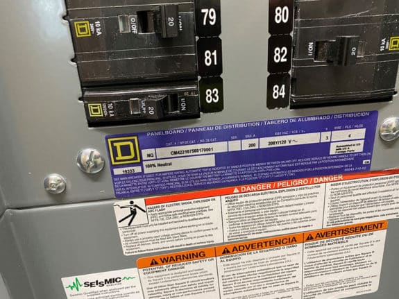
To answer this question, you need to know what voltage is available in the building. This is often dictated by the electrical utility that services the building. More importantly, the voltage(s) available for a specific circuit is determined by the panel from which the circuit is fed.
The following table lists the types of building power distribution systems and the voltages available and the number of breaker poles.
| Distribution Configuration | Voltages Available | Number of Breaker Poles |
|---|---|---|
| 120/240V, 1-phase | 120V | 1 |
| 240V | 2 | |
| 208Y/120V, 3-phase | 120V, 1-phase | 1 |
| 208V, 1-phase | 2 | |
| 208V, 3-phase | 3 | |
| 480Y/277V, 3-phase | 277V, 1-phase | 1 |
| 480V, 1-phase | 2 | |
| 480V, 3-phase | 3 | |
| 208V, 3-phase delta | 208V, 1-phase | 2 |
| 208V, 3-phase | 3 | |
| 240V, split-phase delta or “high-leg delta” | 120V, 1-phase | 1 |
| 240V, 1 phase | 2 | |
| 240V, 3-phase | 3 |
Stay tuned for the next part of this series that explains the differences between distribution configurations.


