Industrial
Bad Vibrations and VFDs: How to Mitigate Premature Motor Damage
By Mike Brandt, PE
The use of Variable Frequency Drives (VFDs) to control electric motors has increased over the last few decades. Not only can they provide control, but they can also increase efficiency and reduce costs through operational energy savings. We have used them on industrial projects to reduce the water hammer in a pumping application or to start a conveyor belt or production process line.
A simple Google search will show you lists of reasons why you should use VFDs, including their ability to:
- Vary a motor’s speed to match the application, saving energy that can’t be done when using other motor starting methods.
- Match the speed of the motor to the process with a single unit versus using a system that requires more energy to run and needs more equipment to reduce its speed.
- Eliminate speed reduction equipment, such as gearboxes, belts, valving, etc., that require maintenance but also add inefficiencies that the motor must drive.
- Adjustable torque limiting.
- Reduce power line disturbances over across-the-line motor starting.
- Operate in reverse operation.
- And several others.
VFDs can also limit a motor’s starting in-rush current, reduce electrical peak demand charges, and ramp up the motor speed to a control setpoint.
Yet, with all the benefits of using a VFD to run an electric motor, there are some inherent disadvantages to consider that will help prevent premature motor failure. One problem we’ve experienced is motor bearing issues on industrial projects. However, after experiencing these issues firsthand, we’ve found two main mitigation techniques that can be put into place to minimize or eliminate these problems.
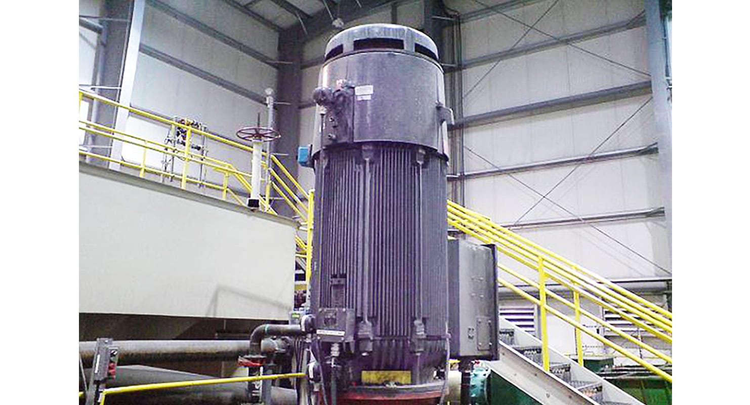
This photo shows a 600 HP, vertically mounted, 480VAC, 3-phase process motor that is connected to a pump to move processed water from a capture facility to a heap leach area. This motor uses a variable frequency drive (VFD) to power the motor and allows it to operate at different speeds. Motor-bearing issues can crop up if steps aren’t taken to mitigate the problem.
Understanding Motor Bearing Currents
Circulating currents that flow through motor bearings—between the stator and the rotor—are not new; they have been present since motors were invented. Before we address the solutions, reviewing how motor-bearing currents work is helpful.
Circulating bearing currents—related to VFDs—are primarily caused by the speed of the inverter switching in the output stage of a VFD. Drives use Pulse Width Modulation (PWM) with semiconductor circuitry to generate the variable frequency and voltage to power the motor at variable speeds. This high switching rate induces a voltage on the motor shaft by parasitic capacitive coupling between the rotor shaft and the stator winding (Read the abstract here).
The film breaks down when the voltage rises above the oil film’s dielectric constant (resistance), usually 20-30V. An electrical discharge occurs, producing a current to flow through the bearings from the rotor to the stator. The motor stator, or the stationary portion of the frame, is bonded to the ground through the equipment grounding conductor in the power feeder. The discharge (when the current passes through the bearings) instantaneously heats and melts the surface of the bearing race at that point and starts to create pitting in the race. This is known as Electrical Discharge Machining (EDM).
Over time, this pitting creates a fluting on the face of the bearing races. When the fluting becomes severe enough, bearings can fail, which causes increased motor vibration. If left unresolved, the motor will fail.
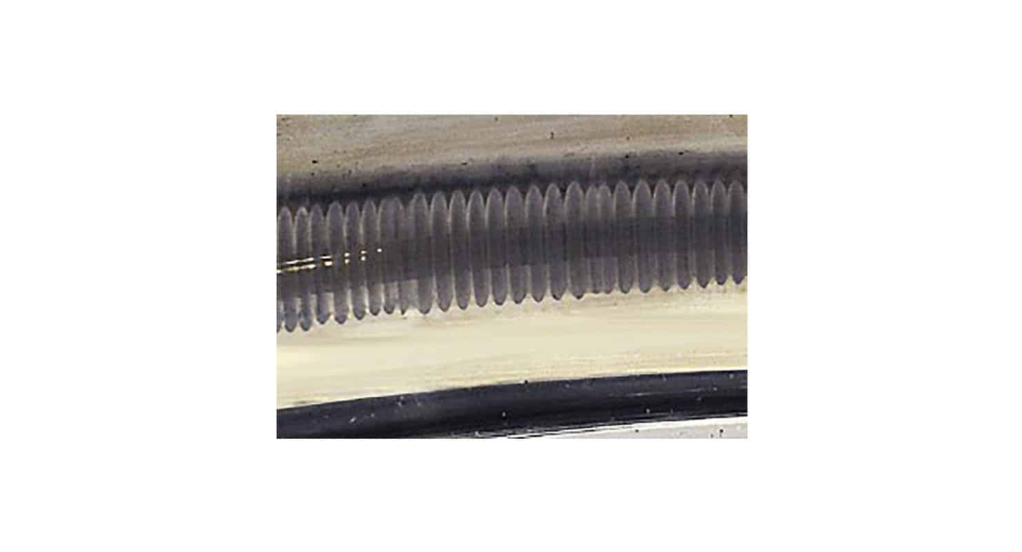
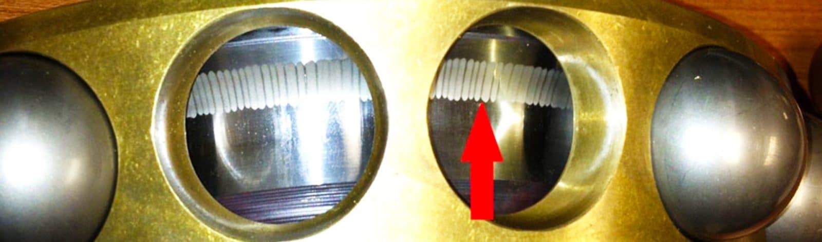
The vertical lines above are the key indicators of fluting on a bearing race. When fluting becomes severe, bearings can fail and leading to increased motor vibration. Photo credit: AEGIS Bearing Protection.
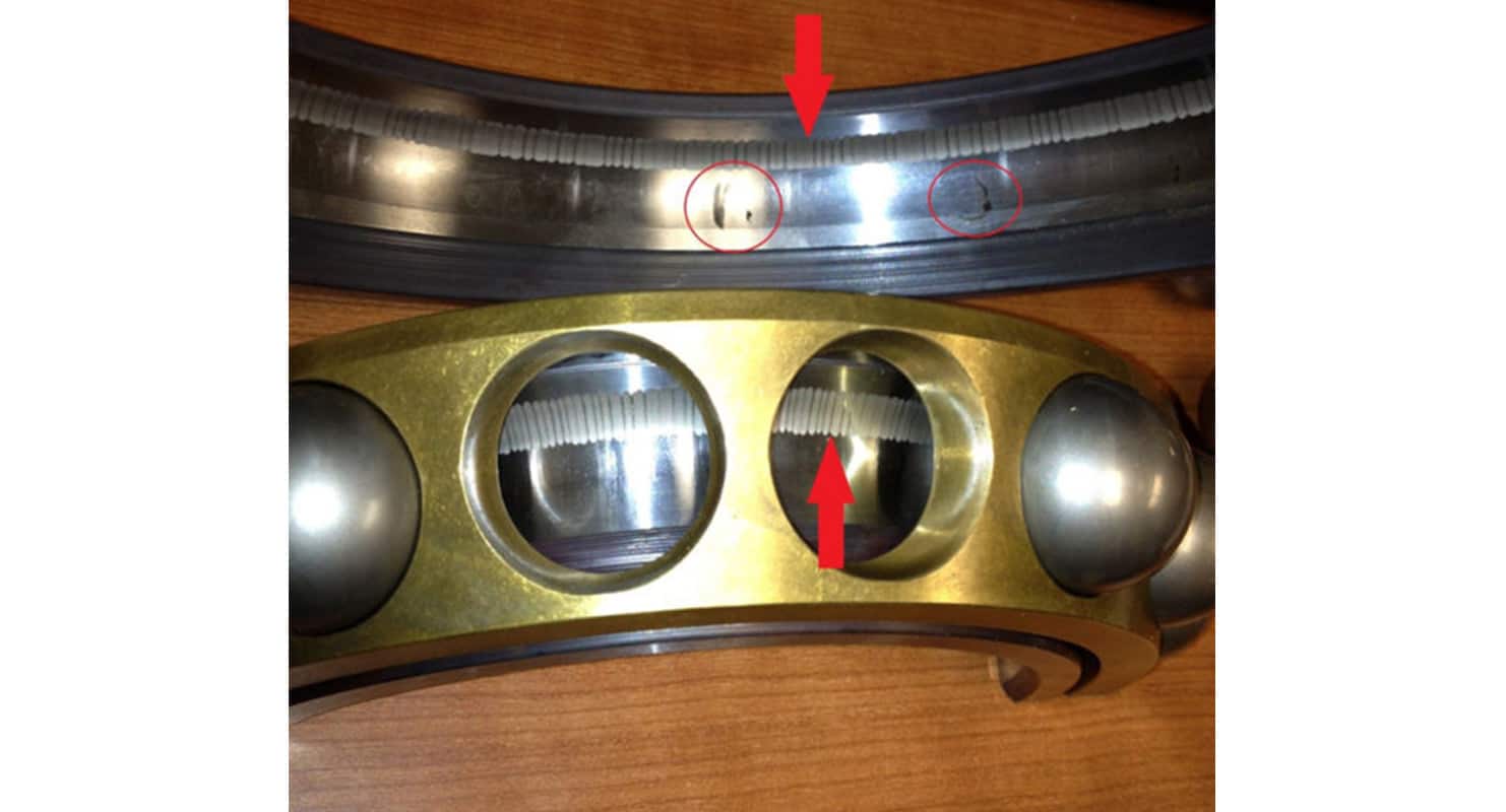
The red arrows show fluting on a 600 HP motor’s inner and outer bearing race.
A Real-World Case
We’ve experienced instances of motor-bearing issues that eventually lead to motor failure. For example, one of our clients was experiencing premature motor failure in some vertically mounted 600Hp process motors. These are 480VAC, 3-phase, VFD-driven motors. The problem was discovered when the motors’ vibration sensors were showing levels above the setpoints in the control and monitoring system. When the motor was removed from service and sent in for repair, the upper motor bearings revealed substantial fluting on both the inner and outer bearing races that indicated a problem.
In this configuration, the upper bearing assembly was under a higher load than the lower bearing assembly. The higher load was causing a thinner oil film, resulting in a lower dielectric value of the oil film. The lower resistance path was providing a connection for the circulating bearing current to pass through the bearings from the rotor to the stator, which resulted in EDM. This caused fluting in both the inner and outer bearing races.
Two Mitigation Strategies
There are numerous strategies for mitigating bearing currents in an electric motor. All strategies involve breaking the current path through the bearings from the rotor to the stator to the ground or providing a low-resistance path to ground from the rotor to the motor case to the ground.
- The first method involves breaking the conductive path by insulating the rotor from the stator. This is accomplished by providing an insulating material, typically ceramic or another non-conductive resin material, between the rotor’s bearing race and the motor case. Another method is to provide ceramic bearings between the rotor and stator. With either of these methods, the circulating shaft current will find another path to the ground. In many applications, the motor shaft is directly coupled to its driving equipment. Direct coupling, through metallic shafts and couplings, provides a low resistance path to ground in the other connected equipment’s bearings which can damage that equipment.
- A second method involves introducing an alternate low-resistance path from the rotor to the ground. This is usually accomplished using a shaft grounding brush or a shaft grounding ring. Both methods require contact with the motor rotor and are subject to wear and contaminants. For example, grounding brushes use spring-loaded metal bristles or a metallic block in constant contact with the rotor and can be internally or externally mounted to the motor housing. This performance is affected by contaminates, oxidation, and heat at higher motor speeds. A good solution involves a shaft grounding ring incorporating conductive microfibers to provide a low-resistance current path to the ground. In this situation, the microfibers are encapsulated in a housing that contacts the entire rotor’s circumference and provides a larger contact area than grounding brushes. These grounding rings are mounted on the exterior of the motor housing around the shaft and bonded to the ground through the motor housing. The microfibers build up less heat, allowing longer service life at higher motor speeds, and appear to have less problem with oxidation. With both methods, remember that the brushes or rings have a service life and need to be replaced and put on a planned preventative maintenance schedule.
Additionally, with any of these strategies, filters on the VFD output are recommended to reduce the PWM voltage spikes before they reach the motor. One option is to add these filters, also called reactors, at the VFD output or the motor. Typically, these are incorporated into a VFD enclosure or Motor Control Center (MCC) bucket that contains the VFD.
Fixing a Real-World Problem
So back to our client’s motor bearing fluting issues. After an investigation, we found that when the motor was rebuilt, the insulated bearing material was not properly installed, resulting in a low resistance path that allowed the current to pass through the upper bearings, which was the cause of the fluting. After the motor was rebuilt properly, they added a grounding brush to prevent any current from passing to the coupled piece of equipment. To date, the motor is still operational and has no further issues.
We’ve found that any motor driven by a VFD is critical to mitigating the motor-bearing currents. And before any remedy is put into place, you should evaluate each solution to maximize service life and reliability and reduce maintenance costs.
If you have VFD-driven motors that seem to have a decreased lifespan or need a new application for a VFD-driven motor, we have some ideas to help you arrive at the best possible solution.
VFD troubles and questions?About The Author

As the Helena Buildings Market Group Office Leader, Mike Brandt leads a team of structural and electrical engineers.
Learn more about MikeRelated Insights